Computer based techniques
Since the 1950s, computer based techniques are used to create relief models [1]. Today, computer-based techniques can convert digital elevation models to real three-dimensional miniature representations of the earth’s surface.
There exist a lot of different techniques for the computer-driven creation of terrain models. They can be divided into subtractive techniques, additive techniques and dynamic techniques [2].
Subtractive techniques
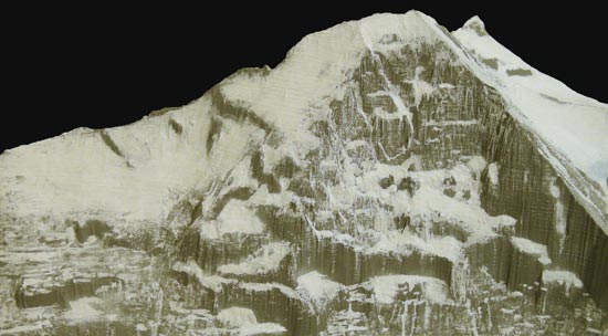
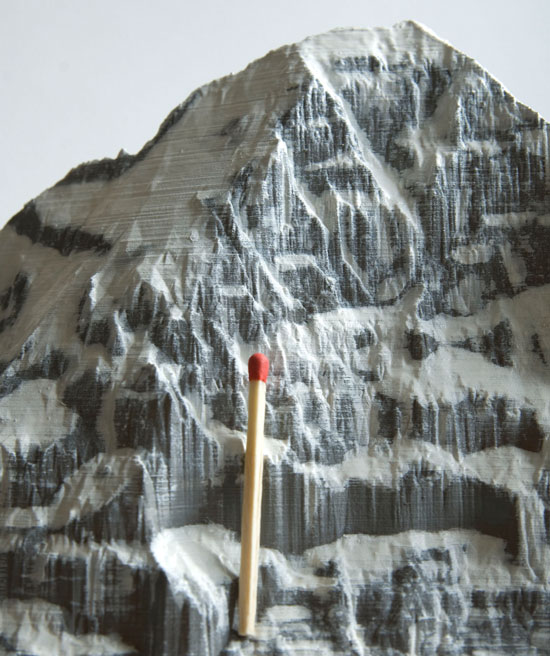
Starting with a block of material like plaster, resin, metal or composites, a milling cutter creates a relief by removing all material above the terrain. The remaining material represents the model. This technique was first used towards the end of the 19th century with the help of a pantograph, milling out material from a block of plaster along the contour lines of a topographical map. In the digital realm, the person guiding the tracing stylus is replaced by a computer. This subtractive technique is the oldest computer-based technique to create terrain models, as it is in use since digital terrain models exist.
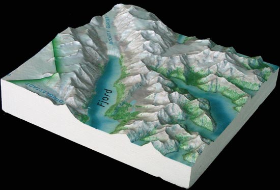
Today, the master models for producing thermoplastic relief models are normally created with this technique. Printing techniques have been developed to print arbitrary images onto the relief models, using modified inkjet technology.
Additive techniques
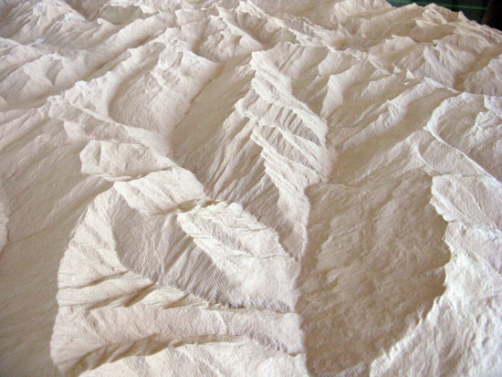
Different techniques were developed that start from a flat base and build the model by adding a series of layers on top of each other. This technique follows the same principle as the manual layer technique used since contour maps were available in the 19th century. In contrast to the subtractive techniques, these methods are able to create cavities and are predestined to model buildings.
This technique, also known as rapid prototyping or 3D-printing, adds layers vertically one by one. The layers, although they may be very thin, usually remain visible at the end of the production process, which is a major disadvantage of this technique.
One additive technique uses stereolithography by tracing a laser beam over a thin layer of a liquid photopolymer that becomes solid when heated by a laser beam. After one layer is finished, the workpiece – situated in a vat of liquid photopolymer – is lowered a little bit so that a new layer of liquid photopolymer covers the model. Then the procedure of tracing the laser beam over the layer is repeated, and finally the whole model is created by iteratively applying this process. Instead of photopolymer, a powder fixed by a binder can be used. The binder is applied by means of an inkjet print head, again layer by layer. Also, a technique using stacked layers of sheets is in use, where each sheet is cut to the correct form by a laser beam.
Dynamic techniques
In the USA, techniques have been developed that allow for the dynamic creation of terrain models. These methods allow generating a model within a few seconds. In the future it might even become possible to create "sandtables" that are able to depict moving landscapes, like it is possible today to move in a virtual three-dimensional representations in flight simulators.
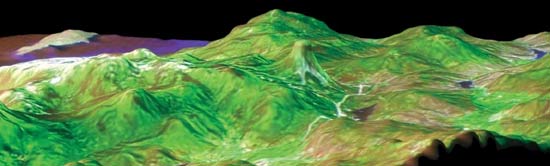
An array of vertical pegs or spikes are mounted on a table, allowing each peg to move vertically. A rubber sheet, lying over this field of rods is pressed onto the pins by means of a vacuum. The different vertical pegs form together an approximated surface of the depicted terrain, while a projector, placed vertically above the model, projects an image (a map or an aerial or satellite image) of the displayed region onto the rubber sheet.
The accuracy of such a model is poor, but it can be changed very quickly, which is obviously very interesting for applications by the army.
[1] See Noma, Arthur A.. Misulia, Michael G.: Programming topographic maps for automatic terrain model construction. In: Surveying and mapping. Vol. 19. No. 3. 1959. p.355-366.